- 您现在的位置:买卖IC网 > Sheet目录1243 > SKP8CMINI-13 (Renesas Electronics America)BOARD DEV EVALUATION FOR R8C/13
�� �
�
�Debugger� Limitations�
�MCU� Applications� Engineering�
�6.0� System� Operation� &� Limitations�
�The� kit� provides� sophisticated� debugging� features� at� a� low� cost� but� it� does� have� some� limitations�
�when� used� with� KD30� Debugger� and� ICD.� Section� 6.1� introduces� the� ROM� monitor� program� and�
�how� it� is� used.� The� limitations� when� this� ROM� monitor� is� running� with� the� user� program� are� listed�
�in� table� 6-1.�
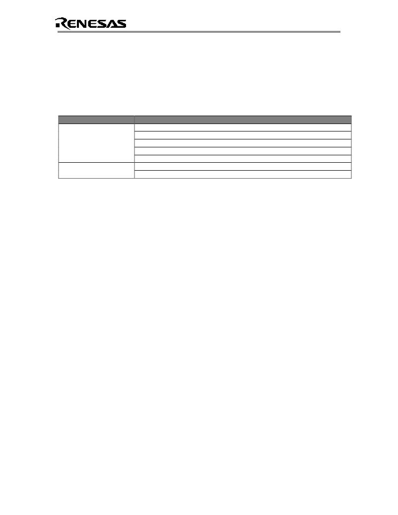
�Table� 6-1� Systems� Limitations� During� Debug� (when� used� with� ICD� +� KD30)�
�Item� Please� Refer� To�
�6.2� Pin� Usage� Limitations�
�6.3� Memory� Map�
�User� Limitations� 6.4� Status� After� Reset�
�6.5� Register� Operation� Limitations�
�6.6� Limitations� on� Interrupts�
�6.7� Stop� or� Wait� Mode� Limitations�
�6.8� User� Program’s� Real-time� Capability�
�6.1� Kernel� (ROM� Monitor)� Introduction�
�During� debug� (used� with� the� KD30� debugger),� a� small� program,� called� a� kernel,� is� downloaded� to�
�the� R8C/13.� The� kernel� communicates� with� the� KD30� Debugger� through� the� ICD� about� MCU�
�status� during� user� code� debugging� operations.�
�There� are� no� special� steps� required� in� the� user� program� to� make� use� of� the� ICD.� The� operation� of�
�the� kernel� is� transparent� to� the� user� but� there� are� some� limitations� and� these� are� discussed� from�
�section� 6.2.�
�After� starting� KD30,� the� ICD� downloads� the� kernel� to� the� R8C/13� if� it� does� not� exist� (e.g.� blank�
�device� or� programmed� with� FoUSB� Programmer).� After� downloading� the� kernel,� KD30� opens� the�
�Program� Window� and� the� R8C/13� is� ready� for� downloading� code.�
�Connecting� the� ICD� without� starting� KD30� will� not� affect� the� lines� connected� between� the� ICD� and�
�the� R8C/13� –� the� ICD� keeps� the� lines� in� high-impedance� state.� The� ICD� only� drives� the� pins� after�
�KD30� or� FoUSB� Programmer� is� started.�
�After� program� debug� and� verification,� you� can� then� create� and� download� a� binary,� Intel� (.hex)� or�
�Motorola� (.mot),� file� to� the� R8C/13.� This� operation� erases� the� kernel� and� only� leaves� the� user�
�program.�
�6.2� Pin� Usage� Limitations�
�SIO/UART1� pins� are� used� for� communication� between� the� Mini� R8C� board� kernel� and� the� host�
�computer� through� the� ICD.� Do� not� connect� these� pins� to� any� other� pins.� UART1� cannot� be� used�
�in� the� user� program.� For� details,� please� see� ICD� (RTA-FoUSB-MON)� User� Manual� Section� 5,�
�Target� M16C� ROM� Monitor� Resources.�
�6.3� Memory� Map�
�Figure� 6-2� shows� the� R5F21134FP� memory� map.� The� user� memory� area� includes:�
�?� RAM� area� –� 1K� Bytes�
�?� Flash� ROM� area� –� 14� KB�
�SKP8CMINI-13� User’s� Manual� Rev.� 1.0�
�11/22�
�October� 2004�
�发布紧急采购,3分钟左右您将得到回复。
相关PDF资料
SKP8CMINI-17
KIT EVAL STARTER FOR R8C/17
SKP8CMINI
DEV EVALUATION KIT R8C/11
SL03 10001
CURRENT LIMITER INRUSH 10 OHM 1A
SL03 22101
CURRNT LIMITER INRUSH 220 OHM 1A
SL05 30001
CURRENT LIMITER INRUSH 30 OHM 1A
SL05 4R003
CURRENT LIMITER INRUSH 4 OHM 3A
SL05 5R001
CURRENT LIMITER INRUSH 5 OHM 1A
SL08 10002
CURRENT LIMITER 10 OHM 2.5A
相关代理商/技术参数
SKP8CMINI-15
制造商:Renesas Electronics Corporation 功能描述:Dev Evaluation R8C/15
SKP8CMINI-17
功能描述:KIT EVAL STARTER FOR R8C/17 RoHS:否 类别:编程器,开发系统 >> 过时/停产零件编号 系列:- 标准包装:1 系列:- 类型:MCU 适用于相关产品:Freescale MC68HC908LJ/LK(80-QFP ZIF 插口) 所含物品:面板、缆线、软件、数据表和用户手册 其它名称:520-1035
SKP8G
制造商:Thomas & Betts 功能描述:PLUG EVERLOK GRD
SKP8GC
制造商:Thomas & Betts 功能描述:PLUG EVLOK SKP8
SKP9G
制造商:Thomas & Betts 功能描述:PLUG EVERLOK GRD
SKP9GC
制造商:Thomas & Betts 功能描述:PLUG MULTI-POLE EVLOK 8W
SKPC100-440
制造商:SEMIKRON 功能描述:SKPC100-440 fair SCR trigger module
SKPC100Z-440
制造商:SEMIKRON 功能描述:TRIGGER MODULE ZERO VOLTAGE 制造商:SEMIKRON 功能描述:SKPC100Z-440 fair SCR trigger module